Confocal microscope
When we see an ideal point by microscope, it can not be seen proper point. We see rings, which causes blur, around the point. The microscope which cut off the rings by putting stop is a confocal microscope. One more feature is spot illumination via an objective lens. Because both illumination and image are focused together, the microscope is described as confocal microscope. But since in this confocal microscope we can see the image only at the one point, scanning is needed for imaging. When focal spot is misaligned in height direction, focal spot of the illumination is also misaligned. Then the image gets dark and invisible. In the confocal microscope, since only the focal spot can be seen brightly, samples can be captured sterically.
In applications for biology, by observing fluorescing dyed samples via confocal microscope, it becomes possible for us to recognaize blurring image as clear and stereoscopic image. This technique is similar to nonlinear optical microscope that can see only fluorescence induced by laser light.
Raman microscope
Raman effect is that light, which wavelength is different from the illuminating light, comes from materials by the illumination of the samples depending on the its condition. Without fluorescing dyeing, the light differenct from excitation comes from. But the light is very weak, the Raman effect could not be realized until strong laser light would appear.
Since Raman scattering light induced by certain incident light is very unique for the materials, it is possible to identify the materials by checking the spectrum of the scattering light. Although the structure of the Raman microscope is similar to that of fluorescence confocal microscope, the Raman microscope has a spectrometer.
Nonlinear optical microscope
Nonlinear optical microscope can see the different light from illumination. Although illumination light is reflected and refracted in the materials, small part of the light is changed its wavelength depending on the condition of the materials. It it also known that the condition of the materials can be changed by strong illumination.
Second harmonic generation microscope
The second harmonic generation (SHG)is a frequency doubled light to an incident light generated in the materials by the incident light. This phenomenon can be applications/ed to shorten (increase) the wavelength (frequency) of the laser light. SHG has many features such that surface state can be studied by seeing SHG intensity which depends on fine structures of the materials, and 3D conformation of the materials can be studied because the SHG is observable only in the illuminated part.
CARS microscope
CARS is a Raman scattering which generates high frequency light rather than incident light. CARS microscope can image the fluorescent biological sample without any dyeing. And it is also possible to know 3D conformation same as SHG microscope.
Electron microscope
Transmission electron microscope (TEM)
Using not light but electron, TEM is the microscope which defeats the limit of spatial resolution in principle. Although electron beam is used for illumination and electron lens which can bend electron beam by electromagnet is used instead of optical lens, a principle of detect image of TEM is same as optical microscope.
Scanning electron microscope (SEM)
Although SEM uses electrons, a principle of detecting an image of SEM is different from the optical microscope in principle. It is more similar to Scanning probe microscope (SPM). By tracing the sample surface with electron beam, which is very narrow sting (probe), an image can be made from the information obtained during the tracing. At first, secondary electrons are observed in SEM. Recently, reflection electron and X-ray, which give a surface composition, can be observed, so that SEM has also been developed for analysis equipment.
Scanning probe microscope
Scanning tunneling microscope (STM)
Using sting as probe, STM measures distance by tunneling effect between sample and sting. As sample is scanned by piezo device precisely, the sting traces over the sample with keeping a certain distance to the sample surface. The position of sample and sting are reconstructed by computer.
Atomic force microscope (AFM)
STM measures tunneling effect, so that it can be utilized for only conductive samples. But AFM can be utilized for insulating sample and sample put under water. Probe is sting as same as STM. By detecting the sting moving by atomic force when the sting sets very near to the sample, the distance in height direction is recorded. As sample scanning is controled precisely by piezo device, the position of sample and sting are reconstructed by compluter same as STM.
Observation with Optical Microscope
This section introduces typical Observation with Optical Microscope in order to learn more about the microscope.
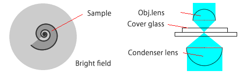
Bright-field Observation
This is the most popular way and everyone experiences this way at school by using microscope. The sample is visible in the bright background when observation of transparent.
This is the observation which can obtain the contrast of the image by illuminating the sample uniformly and measuring the difference in the reflectance and transmittance. This is the same as we see things every day.
But in case of biological, many samples are transparent and mostly colorless. When we see by the method of transparent observation, we can’t obtain a clear contrast. For this reason, method for staining to color the sample was developed.
In transparent observation, the illuminating device is set on the opposite side of objective lens, and we adjust the illumination light to enter the fully objective lens. For this reason, the background of the field of view looks bright. When we observed in reflected light such as metallurgical microscopes, epi-illumination that uses the objective lens as a lens for illuminating is performed.
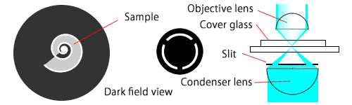
Dark-field Observation
Bright-field Observation is the way to improve unclear, transparent and colorless samples by changing the lighting method. Broadly speaking, it is the way of observation to shed obliquely from the front when the lighting was bright-field.
Place the ring-shaped slip to hide the center in front of the illumination lens. And illumination light is only from the peripheral portion, and oblique light irradiates a sample. In the absence of the sample, illumination light does not enter the objective lens, and the background is dark. In the presence of the sample, the direction of the illumination light is changed by the refraction, and the light enters the objective lens. Then on the part of the sample looks bright. There is a possibility that the sample which is hard to see in bright-field can be seen with contrast. So it is not necessary to stain the sample. The resolution does not mean better, but in such cases there is a very small object on the surface of uniform marginal resolution, which might be easy to find.
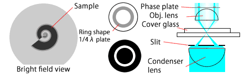
Phase-Contrast observation
It is devised to see the transparent sample without staining of. It is also said that it is a further evolution of Dark-field Observation.
In transparent observation, the light phase is different between the light pass through the sample and did not pass through. This is because the speed of lighting transmitted is changing by material. (affected by diffraction and refraction). But phase difference caused by presence or absence of materials can’t detect by the human eye. This is the method to convert phase difference to contrast utlizaing of the nature of light inference.
Different type illumination and special objective lens are used for this method. For the illumination, illumination light is irradiated on ring-shape area on the sampoel with ring-slit. The objective lens has the phase ring at the pupil.
Light passing trough the sample (phase material or different refractive index) will be affect by the material. Its phase will be shifted with less than quater wave, and its propagation direction will be changed so that the light does not go through the phase material in the objective lens. If the light does not go throug the sample, the light not goes through the phase ring and its phase is shifted in opposite way with phase shift with the sample. The phase difference between the light from the sample and not from the sample gives the interference at the camera and causes the contrast.
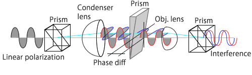
Differential interference contrast observation
This method is similar to Phase-Contrast method in terms of utilizing interference. The different point is that the phase shift is caused by the illumination light path difference between neighbor.
With this method, Nomarski prism is used. After through the prism, the illumination light is splited in two ways with slightly different angle. Each light has different status of polarization (orthogonal). These two lights are focused into neighbor the sample with the objective lens. The distance between two focus is only half spot to one spot. After these two lights pass through the sample, these lights are coupled to one light with another Nomarski prism. If one light pass through the sample of different refractive index, the coupled light intensity will be affected by the interference and as the results, the contrast are give by the interference.
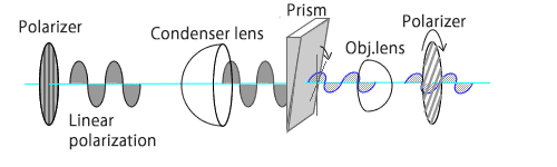
Polarization observation
For anisotropic sample, polarization observation is effective. In polarizaion observation, polarized light is illuminated on sample and the light passing trough the sample is observed though polarizer. When this polarizer is rotated, the sample color will be changed.
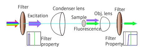
Fluorescence observation
This is the method to see the stained sample with fluorescent dye. Typically the UV or blue light is irradiated on the stained sample. The light will excite the fluorescent dye. The fluorescent light from the dye will be observed easily.